Neo FreeRunner GTA02 Hardware/ru
From Openmoko
m |
(→Кнопочки) |
||
| (16 intermediate revisions by 6 users not shown) | |||
| Line 1: | Line 1: | ||
{{Languages|Neo FreeRunner GTA02 Hardware}} | {{Languages|Neo FreeRunner GTA02 Hardware}} | ||
| − | |||
| − | |||
{{gta02menu}} | {{gta02menu}} | ||
| − | + | Openmoko - это стек программного обеспечения, которое работает поверх [[hardware|аппаратной платформы]]. Смартфон [[Neo FreeRunner]] - это аппаратная платформа второго поколения, которая использует Openmoko. Вы можете получить сведения относительно характериск аппаратной части, просмотрев эту вводную страницу, а также другие страницы в этой категории, приведенные в нижней части этой страницы. | |
<!-- {{note|This page is about hardware that is currently in '''design/prototype''' phase, changes are frequent}} --> | <!-- {{note|This page is about hardware that is currently in '''design/prototype''' phase, changes are frequent}} --> | ||
| − | + | =Резюме= | |
| − | + | Openmoko, Inc. создает основанный на GNU/Linux смартфон применяя для Openmoko микропрограммное обеспечение с исходным кодом, полностью совместимым с условиями лицензии GPL. Кодовое имя проекта GTA02 (Neo FreeRunner). | |
| − | + | ||
| − | + | ||
| − | + | ||
| − | + | Детально аппаратные компоненты рассматриваются далее. См. также [[Neo FreeRunner GTA02 Hardware Requirements\ru]] используемые для выбора этих компонентов. | |
| − | + | ||
| − | + | <gallery> | |
| + | Image:Gta02a5 pcba cs.JPG|нижняя сторона (сторона элементов) NOTE: Фотография стороны элементов в сборе A5 GTA02 | ||
| + | Image:Gta02a5 pcba ps.JPG|верхняя сторона (сторона дисплея) NOTE: Фотография стороны печати в сборе A5 GTA02 | ||
| + | Image:GTA02 A5 PCB CS.jpg|нижняя сторона (сторона элементов) NOTE: Фотография стороны элементов печатной платы A5 GTA02 | ||
| + | Image:GTA02 A5 PCB PS.jpg|верхняя сторона (сторона дисплея) NOTE: Фотография стороны печати печатной платы A5 GTA02 | ||
| + | Image:SimpleComponentDiagram.jpg|Упрощённая диаграма аппаратных компонентов | ||
| + | </gallery> | ||
| − | = | + | == Расположение элементов на печатной плате == |
| − | + | ||
| − | + | {| class="wikitable" cellspacing="2" cellpadding="2" style="padding: 0%; margin:0em 0em 1em 0em; border:1px solid #ffffff; background:#ffffff; width:100%;" | |
| − | + | ! style="background:#ffffff;border-left:1px solid #9999cc;border-right:1px ; border-top:2px solid 75d806; border:1px solid #ffffff; width:33% " | | |
| − | + | <div align=center> | |
| − | + | [[Image:Gta02a5 pcba cs1.png]] | |
| − | + | </div> | |
| − | + | ! style="background:#ffffff;border-left:1px solid #9999cc;border-right:1px ; border-top:2px solid 75d806; border:1px solid #ffffff; width:33% " | | |
| − | + | <div align=left> | |
| − | + | 1. NOR Flash<br/> | |
| − | + | 2. SDRAM<br/> | |
| − | + | 3. GPS<br/> | |
| − | + | 4. CPU/NAND Flash<br/> | |
| − | + | 5. GPU<br/> | |
| − | + | 6. PMU<br/> | |
| − | + | 7. Audio Codec | |
| − | + | </div> | |
| − | + | ! style="background:#ffffff;border-left:1px solid #9999cc;border-right:1px ; border-top:2px solid 75d806; border:1px solid #ffffff; width:34% " | | |
| − | + | ||
| − | + | ||
| − | + | ||
| − | + | ||
| − | + | ||
| − | + | ||
| − | + | ||
| − | + | ||
| − | + | ||
| − | + | ||
| − | = | + | |
| − | == | + | |
| − | + | ||
| − | + | ||
| − | + | ||
| − | + | ||
| − | + | ||
| − | + | ||
| − | + | ||
| − | + | ||
| − | + | ||
| − | + | ||
| − | + | ||
| − | + | ||
| − | + | ||
| − | + | ||
| − | + | ||
| − | + | ||
| − | + | ||
| − | + | ||
| − | + | ||
| − | + | ||
| − | = | + | |
| − | + | ||
| − | + | ||
| − | + | ||
| − | + | ||
| − | + | ||
| − | + | ||
| − | + | ||
| − | + | ||
| − | + | ||
| − | + | ||
| − | + | ||
| − | + | ||
| − | + | ||
| − | + | ||
| − | + | ||
| − | + | ||
| − | + | ||
| − | + | ||
| − | + | ||
| − | + | ||
| − | + | ||
| − | + | ||
| − | + | ||
| − | + | ||
| − | + | ||
| − | + | ||
| − | = | + | |
| − | + | ||
| − | + | ||
| − | + | ||
| − | + | ||
| − | + | ||
| − | = | + | |
| − | + | ||
| − | + | ||
| − | + | ||
| − | + | ||
| − | + | ||
| − | + | ||
| − | + | ||
| − | + | ||
| − | + | ||
| − | + | ||
| − | + | ||
| − | + | ||
| − | + | ||
| − | + | ||
| − | + | ||
| − | + | ||
| − | + | ||
| − | + | ||
| − | + | ||
| − | + | ||
| − | + | ||
| − | + | ||
| − | + | ||
| − | + | ||
| − | + | ||
| − | + | ||
| − | + | ||
| − | + | ||
| − | + | ||
| − | + | ||
| − | + | ||
| − | + | ||
| − | + | ||
| − | + | ||
| − | + | ||
| − | + | ||
| − | + | ||
| + | <div align="left"> | ||
| + | 8. Addio Amplifier<br/> | ||
| + | 9. USB Host Power<br/> | ||
| + | 10. Analog Baseband<br/> | ||
| + | 11. Digital Baseband<br/> | ||
| + | 12. GSM SRAM/Flash<br/> | ||
| + | 13. GSM RF TRanceiver<br/> | ||
| + | 14. RF AMP | ||
| + | </div> | ||
| + | |} | ||
= Аппаратные компоненты GTA02 = | = Аппаратные компоненты GTA02 = | ||
== Габаритные размеры == | == Габаритные размеры == | ||
| − | * 120.7 x 62 x 18.5 | + | * 120.7 x 62 x 18.5 мм (4.75 x 2.44 x 0.728 дюйма) |
| − | * 110 +/- 5 | + | * 110 +/- 5 г (4 унции) без батареи<br> |
== Основные компоненты == | == Основные компоненты == | ||
=== Процессор === | === Процессор === | ||
| − | + | Центральный процессор (CPU) это [[Samsung S3C2442B B54]] (работающий на частоте 400 MHz) | |
| + | |||
| + | Назначение выводов (GPIO): https://svn.openmoko.org/trunk/doc/hardware/GTA02v4/gpio.txt | ||
| + | |||
| − | |||
| − | |||
| − | |||
| − | |||
| − | |||
| − | |||
| − | |||
| − | |||
| − | |||
=== Управление питанием === | === Управление питанием === | ||
| Line 345: | Line 183: | ||
* Driver: http://svn.openmoko.org/developers/sameo/patches/<br> | * Driver: http://svn.openmoko.org/developers/sameo/patches/<br> | ||
| − | == | + | == Виброзвонок == |
* Driver: https://svn.openmoko.org/trunk/src/target/kernel/patches/gta01-vibrator.patch | * Driver: https://svn.openmoko.org/trunk/src/target/kernel/patches/gta01-vibrator.patch | ||
* Connected to: S3C2442 GPIO | * Connected to: S3C2442 GPIO | ||
| Line 366: | Line 204: | ||
* Connect a 15k ohm resistor between d- and ground | * Connect a 15k ohm resistor between d- and ground | ||
* Connect 0V, +5 to your >1A power source | * Connect 0V, +5 to your >1A power source | ||
| − | ** If your power source was not the | + | ** If your power source was not the Openmoko 1A charger, additionally connect a 47K ohm 5% resistor between the ID pin and ground to pretend to be the 1A charger. |
In addition you need to make sure EN_USBHOST signal that enables the physical Host mode power generation and disables the USB -> PMU charging path is deasserted. This may be taken care of automatically shortly by detection of the 48K resistor on a USB insertion leading to forcing EN_USBHOST deasserted. The charge pump that generates the 5V in host mode doesn't seem to mind getting external 5V given to it, but the real issue is that the battery will not be charged at all if we leave EN_USBHOST asserted since one of its jobs is to stop that happening. | In addition you need to make sure EN_USBHOST signal that enables the physical Host mode power generation and disables the USB -> PMU charging path is deasserted. This may be taken care of automatically shortly by detection of the 48K resistor on a USB insertion leading to forcing EN_USBHOST deasserted. The charge pump that generates the 5V in host mode doesn't seem to mind getting external 5V given to it, but the real issue is that the battery will not be charged at all if we leave EN_USBHOST asserted since one of its jobs is to stop that happening. | ||
| Line 413: | Line 251: | ||
4(tip): mic + HOLD-button(press:short to GND) | 4(tip): mic + HOLD-button(press:short to GND) | ||
| − | === | + | === Кнопки === |
| − | + | На Neo1973 GTA02 есть две кнопки: | |
| − | * [[Neo1973 Power Button| | + | * [[Neo1973 Power Button|Кнопка питания]] |
| − | * [[Neo1973 AUX Button| | + | * [[Neo1973 AUX Button|Кнопка "Aux"]] |
== Корпус == | == Корпус == | ||
The case for the FreeRunner is all black, as seen on the front page of the wiki. | The case for the FreeRunner is all black, as seen on the front page of the wiki. | ||
| − | Openmoko has released the CAD files for the case schematics for the | + | Openmoko has released the CAD files for the case schematics for the Openmoko [[Neo1973]] (GTA01) and Neo FreeRunner. These are available in the original Pro/E (.asm/.prt) format and alternative formats created from the originals. |
We welcome your assistance in providing other formats. If you are able to convert CAD files from Pro/E format to other formats, please contact [mailto:michael@openmoko.org]. We are especially interested in the DXF format and in images rendered from these files. | We welcome your assistance in providing other formats. If you are able to convert CAD files from Pro/E format to other formats, please contact [mailto:michael@openmoko.org]. We are especially interested in the DXF format and in images rendered from these files. | ||
| − | * [http://downloads.openmoko.org/CAD/ | + | * [http://downloads.openmoko.org/CAD/NeoFreeRunner_ProE.zip The original Pro/E (.asm/.prt) format] |
[http://downloads.openmoko.org/CAD/ Browse CAD directory] | [http://downloads.openmoko.org/CAD/ Browse CAD directory] | ||
| Line 465: | Line 303: | ||
== GTA02v1 == | == GTA02v1 == | ||
| − | First generation of prototypes that was given to internal | + | First generation of prototypes that was given to internal Openmoko software developers. Total 30 pcs fabricated. |
*It is working just fine, but still based on 2440, with external NAND/SDRAM and no NOR flash | *It is working just fine, but still based on 2440, with external NAND/SDRAM and no NOR flash | ||
| Line 530: | Line 368: | ||
== GTA02v6 == | == GTA02v6 == | ||
| − | + | Версия 3 для массовых поставок<br> | |
| − | A6 | + | A6 это финальная настройка A5, только небольшие изменения в схеме для лучшего качества и контроля версий. Конденсатор и резистор изменен в A6 так же на массовом продукте A5<br> |
| − | * | + | *Первые 100 штук с начала апреля 2008 , и ...factory make component placement mistake on GSM, second 100 pcs PCB arrive time TBD. |
| − | * | + | *Добавлено конденсаторное пространство для Vbat, сокращающее SMT усиление |
| − | * | + | *Добавлен GSM IR резистор для лучшего перехода в сон GSM |
| − | * | + | *Реверсирован 3 GPIO для аппаратного контроля версии |
| − | * | + | *Исправлено потребление LEDs (с 150mW для v5 до 25mW) |
* ATAG_REVISION: 0360 | * ATAG_REVISION: 0360 | ||
| − | === GTA02 A5 | + | === Изменения GTA02 от A5 к A6 === |
| − | * | + | *Питание Glitch on VB_SYS: Добавлен конденсатор, Массовые продукты A5 также применяются эти изменения. |
| − | *G- | + | *G-сенсор разделен на разные выводы прерывания: в A5, каждый акселерометр INT1/INT2 подключён к своей линии, в A6 только INT1 подключен. |
| − | * | + | *GSM_модем источник питания сократил потребление когда по телефону разговаривают |
*Keep active Disable keep active function, just fine tune | *Keep active Disable keep active function, just fine tune | ||
| − | *GPIO | + | *GPIO для контроля версий |
*GSM RX_IR has some noise Add resistor and reduce GSM RX_IR noise and gsm can't enter suspend mode easily, apply on mass production A5. | *GSM RX_IR has some noise Add resistor and reduce GSM RX_IR noise and gsm can't enter suspend mode easily, apply on mass production A5. | ||
*LED driving transistor apply on mass production A5. | *LED driving transistor apply on mass production A5. | ||
| Line 608: | Line 446: | ||
**[http://people.openmoko.org/tony_tu/GTA02/certificate/NCC NCC report and certificate] | **[http://people.openmoko.org/tony_tu/GTA02/certificate/NCC NCC report and certificate] | ||
| − | + | [[Category:Neo FreeRunner Hardware/ru]] | |
| − | + | ||
| − | [[Category:Hardware | + | |
| − | + | ||
| − | + | ||
Latest revision as of 13:14, 3 February 2009
| Languages: |
English • العربية • Български • Česky • Dansk • Deutsch • Esperanto • Eesti • Español • فارسی • Suomi • Français • עברית • Magyar • Italiano • 한국어 • Nederlands • Norsk (bokmål) • Polski • Português • Română • Русский • Svenska • Slovenčina • Українська • 中文(中国大陆) • 中文(台灣) • Euskara • Català |
Neo FreeRunner
Openmoko - это стек программного обеспечения, которое работает поверх аппаратной платформы. Смартфон Neo FreeRunner - это аппаратная платформа второго поколения, которая использует Openmoko. Вы можете получить сведения относительно характериск аппаратной части, просмотрев эту вводную страницу, а также другие страницы в этой категории, приведенные в нижней части этой страницы.
Contents
|
[edit] Резюме
Openmoko, Inc. создает основанный на GNU/Linux смартфон применяя для Openmoko микропрограммное обеспечение с исходным кодом, полностью совместимым с условиями лицензии GPL. Кодовое имя проекта GTA02 (Neo FreeRunner).
Детально аппаратные компоненты рассматриваются далее. См. также Neo FreeRunner GTA02 Hardware Requirements\ru используемые для выбора этих компонентов.
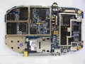
нижняя сторона (сторона элементов) NOTE: Фотография стороны элементов в сборе A5 GTA02
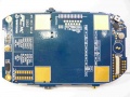
верхняя сторона (сторона дисплея) NOTE: Фотография стороны печати в сборе A5 GTA02
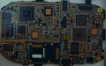
нижняя сторона (сторона элементов) NOTE: Фотография стороны элементов печатной платы A5 GTA02
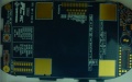
верхняя сторона (сторона дисплея) NOTE: Фотография стороны печати печатной платы A5 GTA02
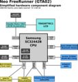
Упрощённая диаграма аппаратных компонентов


[edit] Расположение элементов на печатной плате
|
|
1. NOR Flash |
8. Addio Amplifier |
|---|

[edit] Аппаратные компоненты GTA02
[edit] Габаритные размеры
- 120.7 x 62 x 18.5 мм (4.75 x 2.44 x 0.728 дюйма)
- 110 +/- 5 г (4 унции) без батареи
[edit] Основные компоненты
[edit] Процессор
Центральный процессор (CPU) это Samsung S3C2442B B54 (работающий на частоте 400 MHz)
Назначение выводов (GPIO): https://svn.openmoko.org/trunk/doc/hardware/GTA02v4/gpio.txt
[edit] Управление питанием
A NXP PCF50633 04 N3 is used for power management.
- NXP PMU index: NXP PMU index page
- Product Datasheet: NXP PCF50633 Product Data Sheet
- Product User manual: NXP PCF50633 User Manual
- Special thanks NXP provide full user manual and support openness for all developer
- Datasheet/User manual usage was legally authorized by NXP
- Connected to: S3C2442 via I2C, client address is 0x08.
- Driver Source: https://svn.openmoko.org/trunk/src/target/kernel/patches/pcf50633.patch
[edit] Flash
[edit] NAND Flash
256MB integrated Samsung NAND flash inside the 2442 multi-chip package, attached to the S3C2442 NAND controller
- Product Homepage: S3C2442
- Data Sheet: S3C2442 B54 comes with 256 MB NAND MCP package
- Connected to: S3C2442 NAND controller
[edit] NOR Flash
16MBit ST M58WR016KB706E NOR flash for 'unbrickable emergency boot' feature.
- Product Homepage: ST Mobile Flash NOR/Mobile Terminal
- Data Sheet: M58WR016
- Connected to: S3C2442 NAND controller
[edit] SDRAM
128MB SDRAM (64MB inside 2442 MCP, 1x Samsung K4M51323PC) attached to S3C2442 SDRAM controller
- Product Homepage: Samsung K4M51323PC
- Data Sheet: Samsung K4M51323PC
- Connected to: S3C2442
[edit] GSM/GPRS
The GSM (including GPRS) modem is Texas Instruments Calypso based.
- Connected to: S3C2442 UART1 (full-uart, RxD, TxD, CTS, RTS), /dev/ttySAC0 in userspace
- PM Driver: https://svn.openmoko.org/trunk/src/target/kernel/patches/gta01-power_control.patch
- Accessible GSM/GPRS antenna jack (if battery cover is removed)
[edit] Цифровой модулятор CALYPSO ASIC
Unfortunately we cannot provide many details on the GSM chipset due to very tight NDAs. However, this is not neccessarily required, since it interfaces using a standard UART serial line with the S3C2442. On that interface, GSM 07.05, GSM 07.10 and other standardized protocols are used.
The NDAd documentation for the calypso, register definition and hardware definition was leaked onto a public forum on the 4th of March by persons or persons unknown. The legality of reading these files may vary according to your local laws, as may generating code from them.
- Calypso D751992AZHH
- The firmware within GTA02 should be moko6 or later (internal code name)
[edit] Аналоговый модулятор TI TWL3025BZGMR
- Product Homepage: TWL3014
[edit] TI TRF6151 (GSM/PCS) RF трансивер
- Product Homepage: TRF6151
GPRS Class12/CS4
[edit] AGPS
u-blox ANTARIS 4 chip
- Connected to: S3C2442 UART2, /dev/ttySAC1 in userspace
- Driver: none needed, talks standard NMEA
- u-blox Antaris 4 Protocol Protocol download page
- ATR0635 Datasheet: u-blox ATR0635
[edit] Акселерометры
Two ST LIS302DL
- Homepage: http://www.st.com/stonline/products/literature/ds/12726/lis302dl.htm
- Datasheet: http://www.st.com/stonline/products/literature/ds/12726.pdf
- Connected to: S3C2442 via SPI interface
- S3C2442 SPI EINT interrupt inputs
[edit] Графическое/3D ускорение
Smedia Glamo 3362.
- Homepage: http://www.smediatech.com/product3362.htm
- Driver: https://svn.openmoko.org/trunk/src/target/kernel/patches/smedia-glamo.patch
- Data sheet: This is not available, as it is under NDA. It will likely never be available. (Source: Raster - IRC)
- Connected to: S3C2442 Address/Data bus
[edit] microSD
The GTA02 has one microSD aka Transflash slot. Using the Glamo 3362 MMC/SD controller
- It should support SDHC, and 4GB card has been tested. Anyone with 8GB card? MicroSD slot is under battery.
- Connected to: Glamo 3362 MMC/SD controller
- Driver: Check svn for the SMedia driver with SD implementation
- Supported microSD cards
- Specifications: SD Simplified Specification, MMC (partial), MMC (product manual)
- SANDISK 128 MB/512 MB and some 4G SDHC card been verified could work on GTA02
[edit] LCD модуль (LCM)
Toppoly (tpo) 2.8" diagonal (1.7" x 2.27" - 43mm x 58mm) 480x640 TD028TTEC1 module, using a Toshiba JBT6K74 TFT
LCD Driver Chipset.
- Homepage: Activer-Matrix-VGA.htm
- Specification: FIXME
- Driver: https://svn.openmoko.org/trunk/src/target/kernel/patches/gta01-jbt6k74.patch
- Backlight Driver: https://svn.openmoko.org/trunk/src/target/kernel/patches/gta01-backlight.patch
- Connected to: Glamo3362 LCM interface and Glamo3362 SPI Interface
[edit] Сенсорный экран
- Connected to: S3C2442 TS controller
- Driver: https://svn.openmoko.org/trunk/src/target/kernel/patches/s3c2410_touchscreen.patch
[edit] Модуль Bluetooth
Delta DFBM-CS320 Class2 Module, using CSR BlueCore4
- Data Sheet: 2.DFBM-CS320.pdf
- CSR Data Sheet: CS-101564-DSP10 BlueCore4-ROM Product Data Sheet.pdf
- Driver: Stock Linux Kernel BlueZ
- Connected to: S3C2442 USB Host controller (OHCI)
- PM Driver: https://svn.openmoko.org/trunk/src/target/kernel/patches/gta01-power_control.patch
[edit] Bluetooth аудио
This one is wired via PCM bus from the CSR Bluetooth chip to the Wolfson codec.
[edit] Модуль WiFi
Accton (WLAN 802.11b/g SiP-M WM3236AQ(Flash Ver:2.0 Atheros AR6001GZ)
- Connected to: S3C2442 SDIO Host controller
- Datasheet: Accton 3236AQ datasheet
- Driver: http://svn.openmoko.org/developers/sameo/patches/
[edit] Виброзвонок
- Driver: https://svn.openmoko.org/trunk/src/target/kernel/patches/gta01-vibrator.patch
- Connected to: S3C2442 GPIO
[edit] Хост USB
The USB Host controller is inside the S3C2442
- Driver: Stock Linux kernel ohci_hcd
- USB version 1.1
- Supply USB 5v in Host mode using usb power switch AAT1275IRN-5.0-T1
- A net EN_USBHOST is controlled by PMU GPIO "GPO", this one signal when asserted (high)
- enables generation of 5V for external device using a charge pump
- enables connection of 15K pulldowns to D+ and D- to allow device insertion and removal detection for host mode
- DISABLES the path for USB power to charge the battery
It should also be possible to use host mode with externally-provided power. This will allow the FreeRunner to be connected to a USB device and be powered and charging the battery if present at the same time.
- Connect 0V, d+, d-, +5 to your USB device
- Connect a 15k ohm resistor between d+ and ground
- Connect a 15k ohm resistor between d- and ground
- Connect 0V, +5 to your >1A power source
- If your power source was not the Openmoko 1A charger, additionally connect a 47K ohm 5% resistor between the ID pin and ground to pretend to be the 1A charger.
In addition you need to make sure EN_USBHOST signal that enables the physical Host mode power generation and disables the USB -> PMU charging path is deasserted. This may be taken care of automatically shortly by detection of the 48K resistor on a USB insertion leading to forcing EN_USBHOST deasserted. The charge pump that generates the 5V in host mode doesn't seem to mind getting external 5V given to it, but the real issue is that the battery will not be charged at all if we leave EN_USBHOST asserted since one of its jobs is to stop that happening.
[edit] Устройство USB
The USB Device controller is inside the S3C2442
- Driver: https://svn.openmoko.org/trunk/src/target/kernel/patches/s3c2410_udc.patch
- Please see USB Product IDs on information about which Vendor/Product IDs we use
- 1200mAh lithium battery charges when connected to powered host.
- Mini-AB connector similar to this one.
[edit] Устройство I2C
I2C is a simple communication standard intended to move small amounts of data a few inches between chips.
Please see Neo I2C Devices for more information & a list of devices & the addresses currently in use & documented for the Neo1973.
[edit] Аудио
See also: Neo1973 Audio Subsystem
[edit] Кодек Wolfson
There's a WM8753 Wolfson Microelectronics CODEC (This is not a 'smart' codec that can interpret MP3/... it is a simple dumb 'sound card'.
- Product Homepage: http://www.wolfsonmicro.com/products/WM8753/
- Data Sheet: WM8753.pdf
- Connected to: S3C2442 IIS interface (PCM data), S3C2442 I2C (Control)
- Driver: https://svn.openmoko.org/trunk/src/target/kernel/patches/asoc.patch
[edit] Монофонический усилитель
There's a National Semiconductor LM4853 Mono Amplifier at the analog audio output of the WM8753
- Product Homepage: LM4853.html
- Data Sheet: LM4853.pdf
- Connects to (LM4853 pin):
- S3C2442 GPIO: HP_IN, AMP_SHUT (shutdown);
- Wolfson WM8753: LOUTL (LEFTIN), LOUTR (RIGHTIN);
- speaker4102: (LEFTOUT/BLTOUT-, BLTOUT+);
- headset-jack: ring 2 (RIGHTOUT), ring 3 (LEFTOUT/BLTOUT-) via 1uF-33R each
[edit] Аналоговые проводные наушники
There's a four-ring 2.5mm stereo jack which provides connectivity to old-fashioned wired headsets.
The headsets used by Motorola smartphones (A780,A1200, ...) and the V-360 have a compatible configuration.
ring
1(base): GND
2: right out
3: left out
4(tip): mic + HOLD-button(press:short to GND)
[edit] Кнопки
На Neo1973 GTA02 есть две кнопки:
[edit] Корпус
The case for the FreeRunner is all black, as seen on the front page of the wiki.
Openmoko has released the CAD files for the case schematics for the Openmoko Neo1973 (GTA01) and Neo FreeRunner. These are available in the original Pro/E (.asm/.prt) format and alternative formats created from the originals.
We welcome your assistance in providing other formats. If you are able to convert CAD files from Pro/E format to other formats, please contact [1]. We are especially interested in the DXF format and in images rendered from these files.
[edit] Аксессуары
[edit] Стилус
Using 4 in 1 laser pen
- Vendor: Quarton XPII
- GTA02 standard setup comes with QUARTON XPII 4 in 1 laser pen
[edit] Батарея
The Neo FreeRunner (GTA02) Battery is mechanically and electrically compatible with the Neo1973 GTA01 Battery, as well as limited compatibility with a Nokia BL6C battery. According to this post on the mailinglist. Photo of the battery inside the Neo1973.
- GTA02 using the smart battery based on TI bq27000 chipset
- SANYO UF653450S 1200mAh cell.
- Battery schematics: GTA02 Smart Battery Schematics
[edit] Карта microSD
GTA02 should come with one of following microSD card
[edit] Зарядное устройство
AKII Technology Charger
- Model: A10P1-05MP
- Input: 100-240v~ /0.3A
- Output: +5v up to 2.0A
- Add 47.5k 1% resistor between ID pin and ground for openmoko charger identification
[edit] История
[edit] GTA02v1
First generation of prototypes that was given to internal Openmoko software developers. Total 30 pcs fabricated.
- It is working just fine, but still based on 2440, with external NAND/SDRAM and no NOR flash
- Using the PCF50633 05 N3 due to 04 N3 not available, re-work power for basic schematics verification
- Using GTA01 SIM socket
- Add external debug port
- Still using Global locate A-GPS
- ATAG_REVISION: 0310
[edit] GTA02v2
Second generation of prototypes, Total 50 pcs run at Taipei SMT factory MOUNT
- Ideal is have 256 MB NAND on Samsung package, Due to chip availability Start using S3C2442 B43
- Using correct PMU PCF50633 04 N3
- Change new SIM socket
- Change to u-blox A-GPS
- Change LCM power from 3.3v to 1.8v
- USB power switch layout/pin assignment mistake, could not verify USB host supply 5v function
- GPS function verified ok with good sensitivity
- ATAG_REVISION: 0320
[edit] GTA02v3
Production verification version, 2007/10/11 28 pcs fabricate at FIC SuZhou
- Still using S3C2442 B43 for hardware verification
- Using control pilot run to verify S3C2442 B54 chips
- ATAG_REVISION: 0330
[edit] GTA02v4
Mass production release candidate version 1
2 weeks after v3 gerber out, release the v4 gerber, and 2007/10/20 20 pcs fabricate at FIC SuZhou
- Change LCM power from 1.8v to 3.3v for display stability issue
- fabricate another 200 pcs for yield rate/production verification
- fabricate 50 pcs with S3C2442 B43 (128 MB NAND) for quality comparsion
- USB host power chip have some output voltage stability issues with Vb/Vcc comes from different power source, need layout change to fix the issue
- Battery Coulomb design not working on A4
- ATAG_REVISION: 0340
[edit] GTA02v5
Mass production candidate version 2/Mass production version
- First batch fabricate 2008/1/14 at FIC SuZhou
- Mass production A5 trial run start from 2008 March, including some resistor/capacitor change compare with inital 100 pcs prototypes A5, and prototypes for GTA02 developers was tracked in the Prototypes Page
- Coulomb counter issue fixed
- USB host power switch fixed
- Need add capacitor for PMU Vbat input for stability issue, this could be done by direct SMT or hand rework
- Need rework (still using SMT in production) add capacitor for PMU Vbat input for PMU stability issue.
- Need manual rework GSM IR UART path a 100k pull down for better GSM deep sleep
- ATAG_REVISION: 0350
[edit] GTA02 mass Production version change list
- PMU's LED power error: PMU potential damage issue
- NOR FLASH enable WP: User can write data into NOR FLASH.
- CE CS/RS fine tune: Audio's background noise too high
- I2C pull high resistor: The resistor is too high and signal is distorted
- GSM leakage current: TX_MODEM has a pull high resistor on IO_3V3
- Power consumption: Disable keep active function
- SDIO clock and esd protect resistor
- Refer to Datasheet: R1526 to 33K
- GSM modem on pin: The R1018 is too small and has some leakage current
- LED driving transistor: When GPIO is on, the transistor will be draw more current on LED. This is component change fix, do not need change PCB or re-work.
[edit] GTA02v6
Версия 3 для массовых поставок
A6 это финальная настройка A5, только небольшие изменения в схеме для лучшего качества и контроля версий. Конденсатор и резистор изменен в A6 так же на массовом продукте A5
- Первые 100 штук с начала апреля 2008 , и ...factory make component placement mistake on GSM, second 100 pcs PCB arrive time TBD.
- Добавлено конденсаторное пространство для Vbat, сокращающее SMT усиление
- Добавлен GSM IR резистор для лучшего перехода в сон GSM
- Реверсирован 3 GPIO для аппаратного контроля версии
- Исправлено потребление LEDs (с 150mW для v5 до 25mW)
- ATAG_REVISION: 0360
[edit] Изменения GTA02 от A5 к A6
- Питание Glitch on VB_SYS: Добавлен конденсатор, Массовые продукты A5 также применяются эти изменения.
- G-сенсор разделен на разные выводы прерывания: в A5, каждый акселерометр INT1/INT2 подключён к своей линии, в A6 только INT1 подключен.
- GSM_модем источник питания сократил потребление когда по телефону разговаривают
- Keep active Disable keep active function, just fine tune
- GPIO для контроля версий
- GSM RX_IR has some noise Add resistor and reduce GSM RX_IR noise and gsm can't enter suspend mode easily, apply on mass production A5.
- LED driving transistor apply on mass production A5.
- LCM's VDDIO We can totally power off LCM's power, save about extra 1mA.
[edit] Отладочная плата
[edit] Описание соединения отладочной платы
This is the connector used to connect the Debug Board and possibly other hardware.
Connections are:
- 39 - GND
- 38 - STDI
- 37 - _RESET
- 36 - STMS
- 35 - STCK
- 34 - STDO
- 33 - GSM_EN
- 29 - _STRST
- 19 - X_I2C_SCL (H-TP4703)
- 18 - X_I2C_SDA (H-TP4704)
- 17 - SPI_CLK0
- 16 - SPI_MOSI0
- 15 - SPI-MISO0
- 14 - SS0
- 13 - EINT3 (H-TP4705)
- 3 - CONSOLE_TXD (H-TP4701)
- 2 - CONSOLE_RXD (H-TP4702)
Information from [2].
![[2]](http://people.openmoko.org/roh/Debugport_GTA01bv4.png)
[edit] Отличия аппаратных изменений
[edit] Inside the Bootloader
Every hardware revision has its own u-boot image type. Thus, the bootloader has the revision hard-coded. The hardware revision is passed on to the kernel via the ATAG mechanism (ATAG_REVISION)
[edit] Inside the Kernel
The kernel receives the ATAG_REVISION during bootup, and saves its contents in the "system_rev" global variable.
[edit] From Userspace
The kernel exports the system_rev variable in /proc/cpuinfo as "Revision :" line.
[edit] Certification
[edit] FCC
- For US Import
- 850/1800/1900 Band, FCC ID: EUNGTA02
- 900/1800/1900 Band, FCC ID: EUNGTA02E
- FCC test report(GTA02)
- FCC test report(GTA02E)
[edit] CE
- For Europe
- Registration number: M528583V-EO
- CE report and certificate
[edit] NCC
- For Taiwan Import
- NCC certification number: CCAF08DG0080T0
- NCC report and certificate