Analogue wired Headset Nokia
From Openmoko
m (Removed double title) |
(→HS-47) |
||
| (10 intermediate revisions by 6 users not shown) | |||
| Line 1: | Line 1: | ||
| + | The pinout of Nokia Phones is known to use the [http://forumnokia.com/main/resources/technologies/connectivity/av_connector.html Nokia-wired-conectivity standard], which is: | ||
| − | + | * 1/Tip: left speaker/stereo or main speaker/mono | |
| + | * 2: right speaker/stereo or not connected/mono | ||
| + | * 3: microphone and button (low resistance to ground on press) | ||
| + | * 4/Base: ground | ||
| − | + | This pinout is not compatible to Neo. To use Nokia headphones you have to rewire them swapping Tip and 3. Or use a simple adater doing this swap. | |
| − | + | ||
| − | + | ||
| − | + | ||
| − | + | The following sections describe the modifications made to diferent models of headsets by its owners. | |
| − | + | ||
| − | + | ||
| − | + | ||
| − | + | ||
| − | + | ||
| − | The following sections describe the modifications made to diferent models of headsets by its owners. | + | |
== HS-40 == | == HS-40 == | ||
| − | [http://lists.openmoko.org/pipermail/community/2008-September/029633.html | + | [http://europe.nokia.com/HS-40 Nokia webpage] ([http://lists.openmoko.org/pipermail/community/2008-September/029633.html Mailing list announce]). |
| − | + | ||
| − | + | ||
| − | + | ||
| − | + | ||
| − | + | ||
| − | + | ||
| − | + | ||
| − | + | ||
| − | + | ||
| − | + | ||
| − | + | ||
| − | The upper black piece is now unlocked, and you only have to remove it to see the second screw. | + | To reach the PCB you have to remove the bottom black piece of the gray case. It is glued with a soft adhesive, so simply pull out with a fingernail. Below this you can find one of the two screws. The upper black piece is now unlocked, and you only have to remove it to see the second screw. Now you have opened the case. Remember where the knots of the cables are, and pull out the PCB. You have to swap the red and white wires as seen in the picture (click on the image for full size). |
| − | [[Image:NokiaHS40_disassemble2.jpg]] | + | [[Image:NokiaHS40_disassemble1.jpg|120px]] |
| + | [[Image:NokiaHS40_disassemble2.jpg|150px]] | ||
| + | [[Image:NokiaHS40_disassemble3.jpg|180px]] | ||
| + | [[Image:NokiaHS40_modification.jpg|180px]] | ||
| − | + | You have to change the gain of the output in alsamixer from 80% to 95% due to different sensitivity (dBm/mW) of headphone speakers. Microphone works perfectly. Button may work (not tested). | |
| − | [ | + | == HS-47 == |
| + | [http://europe.nokia.com/HS-47 Nokia Webpage for HS-47] | ||
| − | + | PCB is just slightly different from above HS-40, but same procedure apply : swap red (Right ear) and white (Microphone) cable to match Freerunner plug assignement as seen in the picture (click on the image for full size). | |
| − | [[Image: | + | [[Image:HS-47-wires.jpeg|180px]] |
| − | |||
| − | + | [[Category:Headsets]] | |
Latest revision as of 12:28, 10 January 2010
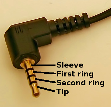
The pinout of Nokia Phones is known to use the Nokia-wired-conectivity standard, which is:
- 1/Tip: left speaker/stereo or main speaker/mono
- 2: right speaker/stereo or not connected/mono
- 3: microphone and button (low resistance to ground on press)
- 4/Base: ground
This pinout is not compatible to Neo. To use Nokia headphones you have to rewire them swapping Tip and 3. Or use a simple adater doing this swap.
The following sections describe the modifications made to diferent models of headsets by its owners.
[edit] HS-40
Nokia webpage (Mailing list announce).
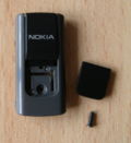
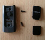
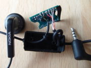
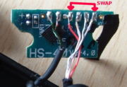
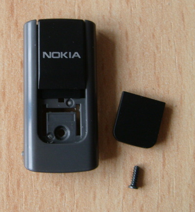
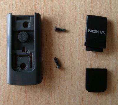
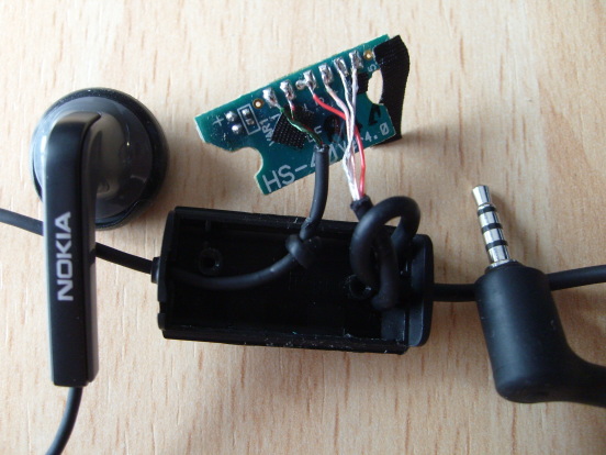
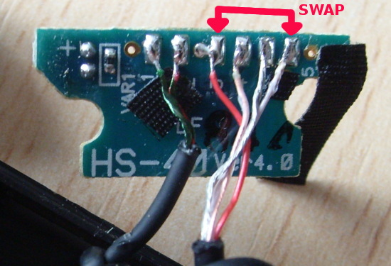
To reach the PCB you have to remove the bottom black piece of the gray case. It is glued with a soft adhesive, so simply pull out with a fingernail. Below this you can find one of the two screws. The upper black piece is now unlocked, and you only have to remove it to see the second screw. Now you have opened the case. Remember where the knots of the cables are, and pull out the PCB. You have to swap the red and white wires as seen in the picture (click on the image for full size).
You have to change the gain of the output in alsamixer from 80% to 95% due to different sensitivity (dBm/mW) of headphone speakers. Microphone works perfectly. Button may work (not tested).
[edit] HS-47
PCB is just slightly different from above HS-40, but same procedure apply : swap red (Right ear) and white (Microphone) cable to match Freerunner plug assignement as seen in the picture (click on the image for full size).

