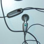
Analog wired Headset Sony Ericsson
From Openmoko
| Line 7: | Line 7: | ||
This pinout is not compatible to Neo. To use this headsets you have to rewire them which requires soldering or usage of a simple adater doing the transformation (however, i currently do not know of any existing). | This pinout is not compatible to Neo. To use this headsets you have to rewire them which requires soldering or usage of a simple adater doing the transformation (however, i currently do not know of any existing). | ||
| − | [[Image:Sony Ericsson headset delivered with P910i, closed.jpg]] | + | |
| − | [[image:Sony Ericsson headset delivered with P910i, soldered to neo layout.jpg]] | + | [[Image:Sony Ericsson headset delivered with P910i, closed.jpg|150px]] |
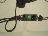
| + | [[image:Sony Ericsson headset delivered with P910i, soldered to neo layout.jpg|200px]] | ||
Revision as of 23:16, 23 December 2008
The pinout of some Headsets delivered by Sony Ericsson are known to use a different pin layout. The layout could is as following (unconfirmed, measuring the pins shows some strange interconections):
- 1/Tip: Mic
- 2: right speaker
- 3: left speaker
- 4/Base: ground
This pinout is not compatible to Neo. To use this headsets you have to rewire them which requires soldering or usage of a simple adater doing the transformation (however, i currently do not know of any existing).
The following sections describe the modifications made to a headset originally delivered with a P910i (there is a small number "Y536Z" inside the case, but i dont know if this is significant).
The modification can be made with the following steps (take care to have a quick but steady hand, the soldering on the image is quite dirty because i had to solder several times):
- unsolder the white cable from the M+ solder contact
- unsolder the two combined green cables from the LS solder contact
- untwist the two green cables so they get separated
- twist the white cable together with the green one from the small grey cable (coming from left speaker)
- solder the white/green cable pair to the LS solder contact
- solder the green cable from the big grey cable to the solder contact M+
- test if everything works now, close the casing if and enjoy stereo sound :)


